Protocols & Signaling 7 min readJun 24, 2026Updated Oct 16, 2026
CORESET and Search Spaces in 5G NR: Where PDCCH Actually Lives
By Gaganpreet Walia
CEO, TELCOMA Global · 21+ years in telecom
In LTE you knew where control was. In NR you go looking for it
In LTE you never had to ask where the control channel was. PDCCH sat in the first 1 to 3 OFDM symbols of every subframe, spread across the entire system bandwidth, and a 2-bit CFI carried on the PCFICH told you whether it was 1, 2, or 3 symbols deep this millisecond (TS 36.211 §6.7, §6.8). Fixed location, whole band, every subframe, every cell. You could point at a resource grid and say "control lives there" without knowing anything about the UE.
NR takes that away on purpose. The control channel didn't get harder to decode — it got unmoored. It no longer sits at the front, it no longer spans the band, and there's no CFI announcing its depth. PDCCH now lives in a CORESET, gets monitored on a schedule called a search space set, and the UE has to find its grant by trying a limited set of candidates blindly. This is the same "fixed became tunable" move that reshaped NR numerology and the resource grid — applied to the one region you used to take for granted.
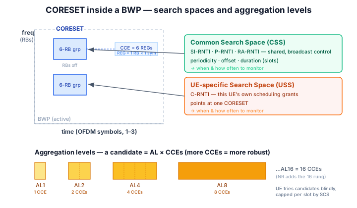
A CORESET drawn inside a BWP showing RB groups by OFDM symbols, with common and UE-specific search spaces pointing at it and aggregation-level candidates of 1, 2, 4, and 8 CCEs.
The CORESET: control became a configured box, not a fixed strip
A CORESET — COntrol REsource SET — is a configurable time-frequency region where PDCCH can live. Two dimensions define it (TS 38.211 §7.3.2.2):
In frequency: a set of 6-RB groups. The allocation is a bitmap, each bit switching a contiguous block of 6 resource blocks on or off. A CORESET is built from 6-RB granules — it does not have to span the whole carrier, and it doesn't have to be contiguous.
In time: 1, 2, or 3 OFDM symbols. Same depth range as LTE's control region — but that's where the resemblance ends.
The headline: a CORESET can sit anywhere inside the Bandwidth Part (BWP). Not pinned to symbol 0, not stretched across the band. The network draws the box where it wants it, sizes it by RRC per BWP, and can beamform it at whoever the grant is for. LTE sized its control region dynamically per subframe with a CFI every UE decoded; NR sizes it semi-statically with RRC, per BWP, per UE. Control stopped being a broadcast property of the cell and became a configured property of the connection.
Inside the box, the building blocks were also redrawn. Carry the LTE numbers over and you'll be wrong:
LTE
5G NR
Control region
first 1–3 symbols, whole band
CORESET: 6-RB groups × 1–3 symbols, anywhere in BWP
Sized by
CFI on PCFICH (per subframe)
RRC, per BWP
REG
4 resource elements
1 RB × 1 symbol (12 REs)
CCE
9 REGs
6 REGs
Aggregation levels
1, 2, 4, 8
1, 2, 4, 8, 16
A REG (Resource Element Group) in NR is one resource block in one OFDM symbol — 12 subcarriers × 1 symbol — where LTE's REG was just 4 REs. A CCE (Control Channel Element), the unit a PDCCH candidate is built from, is 6 REGs in NR versus 9 in LTE. The bricks share names with LTE; the dimensions don't transfer.
There's one CORESET you can't configure away, because it has to exist before RRC does: CORESET#0. It's the bootstrap region, pointed to by the MIB carried in PBCH (the pdcch-ConfigSIB1 field), and it's where a UE doing initial access first looks for the DCI that schedules SIB1. Once SIB1 and dedicated RRC arrive, the network can configure up to 3 CORESETs and 10 search-space sets per BWP and take over from there (TS 38.213 §10.1, §13).
Search spaces: the CORESET is where, the search space is when and how often
This is the split that trips LTE engineers, because in LTE the two ideas were fused. A CORESET tells you where control can physically be. It does not tell you when to look, how often, or which candidate sizes to try. That's a separate object — the Search Space Set (TS 38.213 §10.1).
Keep them cleanly apart:
CORESET = the box. The time-frequency region, built from REGs and CCEs.
Search Space Set = the schedule. It points at one CORESET and adds monitoring occasions — a periodicity, an offset, and a duration in slots — plus how many candidates to attempt at each aggregation level.
A CORESET with no search space pointing at it is monitored never. The search space is what turns a static box into something the UE actually watches on a cadence. These objects are exactly what arrives in the RRC reconfiguration messages — when you debug PDCCH issues, the search-space config in the RRC ASN.1 is the first place to look.
Search spaces come in two flavours, generalising LTE's common-versus-UE-specific idea:
Common Search Space (CSS): shared across UEs, for broadcast and shared-control traffic — system information, paging, random-access responses. DCI here is scrambled by common identifiers (SI-RNTI, P-RNTI, RA-RNTI). The Type0-PDCCH CSS in CORESET#0 carrying the SIB1 grant is the canonical example.
UE-specific Search Space (USS): dedicated to one UE, scrambled by its C-RNTI, carrying that UE's own scheduling grants.
The practical consequence: control monitoring is now per UE and per BWP. Two UEs in the same cell can watch different CORESETs, on different periodicities, at different aggregation levels, on different beams. There is no single control region you can point at for the cell anymore — there are as many monitoring patterns as the network configured.
Aggregation levels: the same robustness dial, one rung taller
A single PDCCH isn't a fixed size — it's assembled from a power-of-two number of CCEs, and that count is the aggregation level (AL). NR supports AL 1, 2, 4, 8, and 16 CCEs (TS 38.211 §7.3.2.1), one rung higher than LTE's 1/2/4/8.
The logic is identical to LTE, and it's the lever the scheduler in the DU's MAC layer pulls for coverage: more CCEs means more coded bits spent on the same DCI payload, which means a lower effective code rate and a more robust transmission. A UE in good conditions near the cell gets its DCI at AL 1 or 2 — cheap, compact. A cell-edge UE, or one buried under a weak beam, needs AL 8 or 16 to land the grant at all. That AL-16 rung exists precisely because NR's beamformed, wide-coverage scenarios occasionally need even more protection on control than LTE ever did. Higher AL buys reliability and pays for it in CCEs — and CCEs are a budgeted resource.
Blind decoding: the UE guesses, within a budget
This is the mechanism that makes the whole flexible-control design work, and it has no clean LTE analogue in scale. The UE does not know, ahead of time, the exact location of its DCI inside the CORESET, nor its aggregation level, nor even which DCI format it'll be. So it does what LTE's UE did, just far more of it: it tries. For each search space, at each configured aggregation level, the UE attempts to decode a set of candidates — trial positions — and checks each with a CRC scrambled by an RNTI it owns. A CRC pass means "this candidate was my DCI." Everything else is discarded. That trial-and-error sweep is blind decoding.
Left unbounded, blind decoding would be ruinous — every extra candidate is another full decode the UE's hardware must run inside one slot, costing silicon and battery. So the spec imposes a hard cap, per slot, that scales with subcarrier spacing (TS 38.213 §10.1). Two limits run in parallel:
a maximum number of monitored PDCCH candidates per slot, and
a maximum number of non-overlapping CCEs the UE must channel-estimate per slot.
The numbers fall as the subcarrier spacing rises, because a wider numerology packs more slots into the same wall-clock time — so a tighter per-slot budget keeps the per-second decoding workload bounded:
SCS
15 kHz
30 kHz
60 kHz
120 kHz
Max PDCCH candidates / slot
44
36
22
20
Max non-overlapping CCEs / slot
56
56
48
32
The ~44-candidates-at-15-kHz figure (TS 38.213 Table 10.1-2, with the CCE budget in Table 10.1-3) is the one to keep in your pocket.
Why does the cap matter to you? Because it turns control capacity into something the scheduler must actively manage. Every UE you configure to monitor PDCCH consumes part of a shared blind-decode and CCE budget. Pile on too many search-space sets, too many candidates, or too many high-AL grants, and you don't get a warning — you bump the ceiling, and the UE simply drops monitoring occasions to stay under it, by a defined priority rule. A grant in a dropped occasion is a grant the UE never sees. If you're chasing a UE that intermittently misses scheduling, this budget is a suspect worth ruling out before you go layer-by-layer through PDCP, RLC, and MAC.
The LTE-engineer gotcha
In LTE, "where is control?" had one answer, true for the whole cell, every subframe, decided by a 2-bit CFI: the front of the band. You reasoned about it globally and never thought of it as a constrained resource. In NR none of that holds:
Control is per-UE, not cell-wide. Each UE has its own search-space configuration; there's no single region to point at.
It's per-BWP and movable. A CORESET sits wherever RRC drew it inside the active BWP, and it moves when the BWP does.
It's beamformed. At FR2 especially, a UE's PDCCH rides a steered beam; "the control region" is a place and a direction.
It's configurable and budgeted. The network sets CORESETs and search spaces by RRC, and the scheduler must fit every UE's monitoring inside a hard per-slot blind-decode and CCE cap that tightens as the subcarrier spacing grows.
If you're moving from LTE to NR and want to drill this on real configs and traces, you can start a free 7-day trial (no credit card) and work through the physical-layer control material hands-on.
The takeaway
CORESET is the box; the search space is the schedule. A CORESET defines where control can live — a set of 6-RB groups by 1 to 3 symbols, placed anywhere in the BWP, built from 6-REG CCEs at aggregation levels 1/2/4/8/16. A search space set defines when and how often the UE looks and which candidates it tries — common (SI, paging, RA) or UE-specific (C-RNTI). The UE finds its DCI by blind decoding, capped at roughly 44 candidates per slot at 15 kHz and falling with wider spacing to protect its power budget. The same shift that reshaped the whole NR air interface versus LTE reached control too: stop assuming where PDCCH is, and start reading the configuration that tells you.
See the grid the CORESET sits in
Three visualisers cover this better than a diagram can: